
Wrinkles in film slitting processes can significantly impact product quality, leading to material waste and customer dissatisfaction. Understanding the root causes and implementing proper control measures ensures consistent, wrinkle-free output from your film slitting machine.
This comprehensive guide covers tension specifications, pressure curve optimization, blade selection criteria, and preventive maintenance protocols. Whether processing BOPP, PET, or specialty films, these proven techniques help maintain quality standards while maximizing productivity.
What Causes Film Wrinkles During Slitting?
Film wrinkles form when uneven tension distribution, improper pressure settings, or mechanical misalignment disrupts the web path. Primary causes include air entrapment between layers, inadequate tension control across web width, and roller geometry issues.
Material properties also influence wrinkle formation. Thinner films require precise tension control, while thicker materials need appropriate pressure curve adjustments. Environmental factors like temperature and humidity affect film behavior during processing.
Types of Wrinkles in Film Slitting
Longitudinal wrinkles run parallel to the machine direction, typically caused by uneven cross-web tension or roller misalignment. These appear as continuous streaks affecting multiple rolls.
Transverse wrinkles form perpendicular to the web direction, often resulting from improper winding tension or pressure roller settings. Bottom wrinkles indicate air entrapment issues requiring pressure curve adjustment.
Film Slitting Machine Setup Parameters
Proper machine setup prevents most wrinkle issues before they occur. The following specifications provide baseline settings for common film materials:
| Parameter | BOPP Film | PET Film | PE Film | Application Notes |
|---|---|---|---|---|
| Web Tension (N/m) | 80-120 | 100-150 | 60-100 | Adjust ±10% for thickness variations |
| Slit Width Tolerance (mm) | ±0.5 | ±0.3 | ±1.0 | Tighter tolerance for thin gauge |
| Blade Angle (degrees) | 45-60 | 30-45 | 60-75 | Shear cut standard; razor for <50μm |
| Knife Overlap (mm) | 0.5-1.0 | 0.3-0.8 | 1.0-1.5 | Increase for thicker materials |
| Pressure Roller Load (N/cm) | 20-40 | 30-50 | 15-30 | Progressive increase during winding |
| Core Shaft Expansion (bar) | 4-6 | 5-7 | 3-5 | Differential shaft for tension control |
Tension Zone Configuration
Unwind tension maintains web stability while preventing material stretching. Set initial tension at 60-70% of running tension, gradually increasing as roll diameter decreases.
Process zone tension between slitting and rewinding requires precise control. Maintain consistent tension across web width using bowed rollers or segmented tension rollers for films wider than 1000mm.
Rewind tension determines roll hardness and prevents telescoping. Taper tension reduces from 100% at core to 40-60% at full diameter, preventing spoke formation and maintaining roll integrity.
How to Calculate Proper Slitting Tension?
Calculate base tension using material yield strength and thickness. For films, use 10-15% of yield strength as maximum tension to prevent permanent deformation. Adjust for web width using the formula: Tension (N) = Specific Tension (N/m) × Web Width (m).
Factor in speed variations by reducing tension 5-10% for every 100 m/min increase above base speed. Temperature compensation requires 2-3% tension reduction per 10°C above standard conditions.
Pressure Curve Optimization
Pressure curves control contact roller force throughout the winding cycle. Start with minimal pressure (10-20% of maximum) to prevent bottom wrinkles from air entrapment.
Linear pressure increases work for uniform thickness materials. Use progressive curves for films with gauge variations, adjusting slope based on thickness profile data.
Maximum pressure depends on material compressibility and roll diameter. Typical endpoints range from 30-50 N/cm for soft films to 80-100 N/cm for rigid materials.
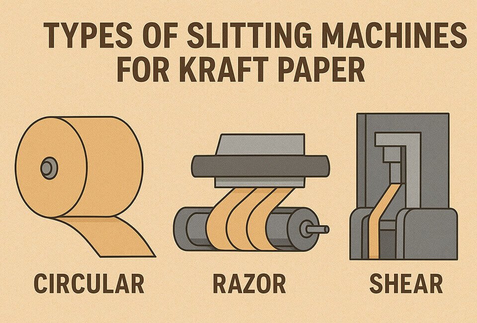
Blade Selection and Positioning Guide
Shear slitting provides clean edges for films 50-500μm thick. Position top and bottom blades with proper overlap and side clearance based on material properties.
Razor slitting suits thin films under 50μm, requiring precise blade angle control. Mount blades at 15-30° angle, adjusting penetration depth to 10-20% of material thickness.
Crush cutting works for thick, rigid films over 250μm. Maintain knife pressure at 150-200% of material shear strength while ensuring anvil roll hardness exceeds 90 Shore A.
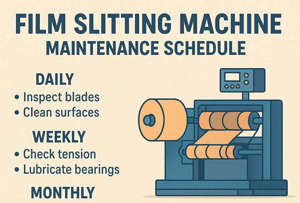
Blade Maintenance Schedule
Inspect blade edges every 8 operating hours using 10x magnification. Replace when edge radius exceeds 0.05mm or visible nicks appear.
Rotate blades based on linear meters cut: every 50,000m for abrasive materials, 100,000m for clean films. Track blade performance by monitoring edge quality and dust generation.
Clean blade assemblies during each changeover. Remove adhesive buildup using appropriate solvents, avoiding damage to cutting edges or mounting surfaces.
Pre-Operation Setup Checklist
Systematic setup procedures prevent wrinkle formation and ensure consistent quality. Follow this sequence before each production run:
Material Inspection
Check incoming roll quality for gauge variations, surface defects, and core integrity. Measure thickness at multiple points across width, rejecting rolls with >5% variation.
Verify material conditioning meets specifications. Films require 24-hour temperature stabilization and humidity equilibration before processing.
Inspect core dimensions and concentricity. Out-of-round cores cause tension variations leading to wrinkles and telescoping.
Machine Alignment Verification
Check roller parallelism using precision straight edge or laser alignment system. Maximum deviation: 0.05mm per meter of roller length.
Verify web path geometry ensures proper wrap angles. Minimum wrap angle of 15° on tension sensing rollers, 30° on driven rollers.
Confirm knife holder alignment within 0.02mm across slitting width. Misalignment causes uneven slit widths and edge quality issues.
Environmental Control Requirements
Temperature fluctuations affect film properties and tension stability. Maintain processing area at 20-25°C with ±2°C stability during production runs.
Relative humidity between 45-55% prevents static buildup and dimensional changes. Install humidification systems for facilities in dry climates.
Air circulation removes heat from friction points while preventing contamination. Use filtered air systems with 5-10 air changes per hour.
Static Control Methods
Install passive static eliminators at unwind, slitting, and rewind stations. Position ionizing bars 25-50mm from web surface for optimal effectiveness.
Active static control systems work better for high-speed operations above 300 m/min. Adjust ion balance to maintain web charge below 2kV.
Conductive roller coverings and grounded machine frames provide additional static dissipation. Maintain ground resistance below 1 megohm.
Troubleshooting Matrix for Common Defects
| Defect Type | Symptoms | Root Causes | Corrective Actions |
|---|---|---|---|
| Bottom Wrinkles | Wrinkles in first 5-10 layers | Air entrapment, low initial pressure | Increase starting pressure, add lay-on roller |
| Telescoping | Lateral roll shift >2mm | Uneven tension, poor core grip | Balance cross-web tension, increase core pressure |
| Edge Burr | Raised material at slit edge | Dull blades, improper overlap | Replace blades, adjust knife positioning |
| Dust Generation | Particles on film surface | Blade wear, material abrasion | Install extraction system, optimize blade angle |
| Spoke Formation | Hard bands in roll | Excessive rewind tension | Reduce tension taper, adjust pressure curve |
| Tin-Canning | Buckled roll edges | Uneven cross-web tension | Check spreader roll function, verify alignment |
Dust Extraction System Design
Edge trimming generates particles requiring immediate removal. Position extraction nozzles within 50mm of cutting point with 20-30 m/s capture velocity.
Slitting dust extraction requires distributed suction across web width. Install slotted extraction bars with adjustable dampers for different slit configurations.
Filter systems must handle particle sizes from 0.5-50 microns. Use progressive filtration with pre-filter, main filter, and HEPA final stage for clean room applications.
Extraction System Specifications
Calculate required airflow based on web speed and material type. Standard films need 10-15 m³/min per meter of slitting width.
Maintain transport velocity above 18 m/s in ductwork to prevent particle settling. Size ducts for 20% excess capacity to accommodate filter loading.
Monitor filter differential pressure to schedule maintenance. Replace filters when pressure drop exceeds 150% of clean filter baseline.
Operator Training Protocol
Effective operator training reduces defects and improves response to process variations. Structure training in progressive modules covering theory and hands-on practice.
Basic Operation Skills
Web threading procedures ensure proper tension establishment. Train operators to recognize correct wrap angles and tension indicators.
Knife positioning requires understanding of overlap and clearance effects. Practice setups with different material types develop positioning skills.
Quality inspection techniques identify defects early. Train visual and tactile inspection methods for edge quality and roll formation.
Advanced Troubleshooting
Tension profile analysis helps diagnose wrinkle causes. Teach data collection and interpretation using tension mapping tools.
Pressure curve optimization requires understanding material behavior. Practice adjustments while monitoring roll hardness and formation quality.
Preventive maintenance execution extends equipment life. Train inspection procedures, lubrication schedules, and component replacement criteria.
Quality Metrics and Measurement
Edge quality assessment uses optical measurement for burr height and edge straightness. Maintain burr height below 5% of material thickness.
Slit width accuracy requires sampling across roll width and length. Use statistical process control with Cpk >1.33 for critical dimensions.
Roll formation quality includes hardness profile, diameter consistency, and end face alignment. Measure using durometer and profile scanning systems.
Documentation Requirements
Setup sheets record all machine parameters for each product. Include tension settings, pressure curves, blade configurations, and environmental conditions.
Quality logs track defect occurrences and corrective actions. Analyze trends to identify recurring issues requiring systematic solutions.
Maintenance records document all service activities. Track blade changes, alignment checks, and component replacements for reliability analysis.
Conclusion
Preventing wrinkles in film slitting machine operations requires systematic attention to setup parameters, environmental controls, and operator procedures. Implementing these specifications and protocols ensures consistent quality output.
Regular maintenance, proper blade selection, and optimized pressure curves form the foundation of wrinkle-free production. Combined with comprehensive operator training and quality monitoring, these practices maximize both productivity and product quality.
Success in film slitting depends on understanding material behavior and machine capabilities. Apply these guidelines while adapting to specific material requirements and production demands for optimal results.
Glossary
- Burr
- Raised edge material resulting from improper blade sharpness or positioning during slitting operations
- Telescoping
- Lateral shifting of wound layers causing roll ends to form a slanted or stepped appearance
- Differential Shaft
- Rewind shaft with independent torque control for each slit roll, enabling individual tension adjustment
- Lay-on Roller
- Contact roller applying controlled pressure to eliminate air between winding layers
- Wrap Angle
- Arc of contact between web and roller surface, affecting traction and tension sensing accuracy
- Knife Overlap
- Vertical distance between top and bottom circular blades in shear slitting configuration
- Spoke Formation
- Hard radial bands in wound rolls caused by excessive tension during initial winding layers
- Nip Point
- Line of contact between pressure roller and winding roll where air exclusion occurs