

Operating a film slitting machine requires strict adherence to safety protocols. These procedures prevent injuries and ensure consistent production quality. This comprehensive checklist covers critical safety procedures from pre-operation inspections through emergency response protocols.
Safety guidelines protect operators while maintaining optimal web tension control and edge quality. These protocols apply whether you’re slitting polyester, polypropylene, or specialty films throughout the converting process.
What PPE is Required for Film Slitting Machine Operation?
Personal protective equipment selection depends on the specific operation phase and material being processed. Cut-resistant gloves rated ANSI A4 or higher are mandatory during blade handling. Safety glasses with side shields protect against film particles during high-speed slitting.
Hearing protection becomes essential when operating speeds exceed 300 meters per minute. Anti-static footwear prevents electrostatic discharge buildup when processing films with low surface resistivity below 10^12 ohms/square.
| Operation Phase | Required PPE | ANSI/CE Rating | Material-Specific Requirements |
|---|---|---|---|
| Blade Change | Cut-resistant gloves | ANSI A4-A5 | Kevlar-lined for razor blades |
| Web Threading | Safety glasses | Z87.1+ | Anti-fog coating for PVC |
| Core Handling | Steel-toe shoes | ASTM F2413 | 75lb impact rating minimum |
| Static-prone films | ESD footwear | EN 20345 | Resistance 10^5-10^8 ohms |
| Dust extraction | N95 respirator | NIOSH approved | Required for edge trimming |
Lockout/Tagout Procedures for Slitting Equipment
Energy isolation through proper lockout/tagout (LOTO) prevents unexpected machine startup during maintenance. Each film slitting machine contains multiple energy sources requiring systematic isolation. All service work requires complete energy isolation before beginning.
Primary Energy Isolation Points
Main electrical disconnect switches control primary power to drive motors and control systems. Pneumatic supply valves must be locked closed with system pressure bled to zero. Use designated relief valves for safe pressure discharge.
Hydraulic systems require specific shutdown procedures. First, shut down the pump and activate pressure relief valves. Then verify accumulator discharge before proceeding with any maintenance work.
Mechanical energy stored in wound rolls needs controlled release. Use manual unwinding or tension release mechanisms to safely dissipate stored energy.
Step-by-Step LOTO Sequence
Begin by notifying all affected personnel before initiating lockout procedures. Stop the machine using normal shutdown sequence. Verify all motion has ceased completely before proceeding.
Follow this electrical isolation sequence:
- Switch main electrical disconnect to OFF position
- Apply assigned lock with identification tag
- Test controls to verify zero energy state
For pneumatic systems, close and lock the supply valve first. Then activate pressure relief to exhaust residual air. Monitor pressure gauges to confirm complete depressurization.
Hydraulic lockout requires these steps:
- Shut down pump motor and lock disconnect switch
- Open hydraulic relief valve
- Verify system pressure drops below 50 PSI
- Document lockout completion on daily safety checklist
How to Safely Change Blades on Different Slitter Types?
Blade replacement procedures vary between shear, razor, and crush-cut slitting systems. Each configuration requires specific safety protocols to prevent lacerations. Proper blade alignment ensures both operator safety and cut quality.
Shear Slitting Blade Change Protocol
Always verify complete lockout/tagout before accessing the blade area. Begin blade removal by loosening mounting bolts from outer positions toward center. This sequence prevents binding and maintains control during removal.
Support the bottom blade with a designated holding fixture during removal. Extract blades using specialized removal tools designed for your specific machine. Never attempt manual removal without proper equipment.
Prepare mounting surfaces by cleaning with lint-free cloth. Inspect for damage or wear exceeding 0.002 inches. Any surface irregularities compromise both safety and cut quality.
Install new blades following these specifications:
- Orient cutting edge according to rotation direction markers
- Torque mounting bolts to 25-35 ft-lbs for 1-inch diameter blades
- Verify blade clearance of 0.0015-0.003 inches using feeler gauges
- Check clearance at multiple points along blade length
Razor Blade Replacement Safety
Razor blades require extreme caution due to exposed cutting edges. Use magnetic blade holders to maintain positive control during removal and installation. This prevents accidental drops or contact with sharp edges.
Inspect blade holder assemblies before installing new blades. Replace worn holders showing groove depth exceeding 0.010 inches. Worn holders compromise blade stability and increase injury risk.
Set blade exposure between 0.5-2.0mm based on film thickness. Use a precision depth gauge for accurate measurement. Excessive exposure increases injury risk without improving cut quality.
Material-Specific Safety Hazards and Controls
Different film materials present unique safety challenges requiring targeted control measures. Static electricity poses risks with certain polymers while others generate harmful dust. Understanding material-specific hazards enables proper protective measures.
| Material Type | Primary Hazard | Control Method | Monitoring Requirements |
|---|---|---|---|
| Polyester (PET) | Static buildup >20kV | Ionizing bars at 6″ spacing | Monthly static meter checks |
| Polypropylene (PP) | Edge dust accumulation | Extraction @ 400 CFM/blade | Weekly filter inspection |
| PVC Films | Plasticizer migration | Nitrile gloves required | Quarterly exposure monitoring |
| Metalized films | Conductive particles | Grounded equipment/operators | Daily resistance testing |
| Release liners | Silicone contamination | Dedicated blade sets | Surface energy testing |
Static Electricity Control Requirements
Electrostatic discharge poses both safety and quality risks during film slitting operations. Static charges exceeding 15kV can cause operator shock and film adhesion problems. High static levels also create potential ignition risks with flammable vapors.
Active Ionization Systems
Install static elimination bars within 6 inches of the web path at critical points. Position bars at the unwinder, slitting station, and rewinder for comprehensive coverage. AC ionization systems provide balanced ion generation for charges up to 50kV.
Pulsed DC systems offer superior performance for high-speed applications exceeding 500 meters per minute. These systems respond faster to rapidly changing charge levels. Monitor ionization effectiveness using handheld static meters at designated test points.
Passive Grounding Methods
Maintain equipment grounding resistance below 10 ohms through dedicated ground conductors. Test grounding connections monthly using a ground resistance tester. Document all test results for compliance verification.
Install conductive brushes or tinsel at idler rolls to dissipate accumulated charges. Position these passive devices to maintain continuous contact with roll surfaces. Replace worn brushes when bristle length decreases by 50%.
Control ambient humidity between 50-60% RH to reduce static generation. Monitor conditions continuously using calibrated hygrometers. Adjust humidity levels as needed for sensitive materials.
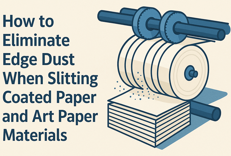
Dust Extraction System Design Requirements
Edge trimming and slitting operations generate particulates requiring engineered extraction systems. Proper dust control prevents respiratory hazards while maintaining cut quality. System design must accommodate various film types and operating speeds.
Extraction Capacity Calculations
Design extraction systems for minimum 400 CFM per slitting blade for films under 100 microns. Increase capacity to 600 CFM per blade for thicker materials. High-speed operations above 300 m/min require the higher extraction rate.
Position extraction hoods within 2 inches of the cutting point for maximum effectiveness. Use adjustable mounting to accommodate different slit widths. Maintain duct velocity of 3500-4000 FPM to prevent particle settling.
Filtration Requirements
Primary filtration using pleated cartridge filters rated MERV 11 or higher captures particles down to 1 micron. Select filter media compatible with the specific dust characteristics. Some films generate sticky particles requiring special filter treatments.
Secondary HEPA filtration may be required for films containing hazardous additives. Verify local air quality regulations for specific requirements. Document filter efficiency testing results annually.
Monitor filter pressure drop using magnehelic gauges installed across each filter bank. Replace filters when differential pressure exceeds 4 inches water column. Document filter changes on the preventive maintenance schedule.
Emergency Response Procedures
Rapid response to emergency situations minimizes injury severity and equipment damage. All operators must know emergency stop locations and response protocols. Regular drills ensure proper execution during actual emergencies.
Emergency Stop System Requirements
Install emergency stop buttons within 3 feet reach of all operator positions. Wire E-stops in series to ensure any activation stops all motion. Machine motion must cease completely within 2 seconds of activation.
Test emergency stop function weekly using this procedure:
- Activate each button individually during normal operation
- Time the duration from activation to complete stop
- Document test results in maintenance log
- Address any stops exceeding 2-second requirement immediately
Web Break Response Protocol
Web breaks require immediate response to prevent material wrapping and equipment damage. Upon detecting a break, immediately activate the nearest emergency stop. Alert nearby personnel using the designated alarm signal before approaching.
Wait for all rollers to stop completely before attempting to clear wrapped material. Even slowly rotating rolls can cause severe entanglement injuries. Use designated cutting tools to remove wrapped film safely.
Inspect all affected rollers for damage before re-threading the web. Replace any rolls showing surface damage exceeding 0.001 inches depth or 1/4 inch length. Document all damage and repairs in the maintenance log.
Pre-Operation Safety Inspection Checklist
Systematic pre-shift inspections identify potential hazards before they cause incidents. Use this checklist to verify all safety systems function properly. Document any deficiencies and correct them before starting production.
Mechanical Safety Devices
Begin inspection with physical guarding systems. These primary barriers prevent operator contact with hazardous machine parts.
- Verify all guards are in place and securely fastened
- Check guard interlock switches for proper operation
- Inspect blade guards for damage or excessive wear
- Confirm safety light curtains activate at 6-inch penetration
- Test pull-cord emergency stops along operator walkways
Electrical Safety Systems
Electrical safety devices protect against shock hazards and equipment damage. Test these systems according to manufacturer specifications.
- Verify ground fault circuit interrupters function correctly
- Check control voltage (typically 24VDC) at operator stations
- Inspect power cables for damage or exposed conductors
- Confirm motor overload settings match nameplate ratings
- Test beacon lights and audible alarms for proper operation
Web Threading Safety Procedures
Threading new material through the slitting line presents multiple pinch point hazards. Following proper procedures prevents entanglement injuries during this critical operation. Never rush the threading process to save time.
Pinch Point Identification
Mark all nip points with high-visibility warning labels specifying minimum clearance distances. Primary hazard zones include pull rolls, slitting stations, and winding nips. Update labels whenever equipment modifications change hazard locations.
Maintain minimum 4-inch clearance between operators and rotating elements during threading. Use threading ropes or tapes to maintain safe distance. These tools allow web control without placing hands near hazards.
Threading Sequence Protocol
Run the machine at threading speed (typically 10-30 meters per minute) during the entire operation. Production speeds create unacceptable risks during threading. Program threading speed limits into machine controls when possible.
Station operators at designated positions with clear sight lines. Establish communication protocols using standardized hand signals or two-way radios. Verify all operators understand signals before beginning.
Thread one section at a time following this sequence:
- Secure web at each section before proceeding
- Verify proper tracking and alignment
- Check tension settings for threading mode
- Confirm all operators are clear before advancing
- Increase to production speed only after complete threading
Blade Handling and Storage Safety
Proper blade handling prevents lacerations while maintaining cutting edge integrity. Sharp blades require respect and systematic handling procedures. Establish dedicated protocols for blade transport, storage, and disposal.
Blade Transport Protocols
Transport blades in designated carriers with individual slots preventing blade-to-blade contact. Each carrier should accommodate specific blade types and sizes. Label carriers clearly with blade specifications and sharpness status.
Carry blade containers with two hands, maintaining a stable grip throughout transport. Keep containers level to prevent blade shifting. Never stack blade carriers or place other items on top during movement.
Storage Requirements
Store blades in locked cabinets with segregated sections for new, used, and damaged blades. Proper organization prevents accidental contact with sharp edges. Maintain storage area humidity below 50% to prevent corrosion.
Apply light machine oil coating to carbon steel blades for rust prevention. Use only manufacturer-recommended oils to avoid contamination. Document blade inventory including receipt date, usage hours, and disposal date.
Implement a blade tracking system recording:
- Purchase date and supplier information
- Installation and removal dates
- Total running hours or linear meters cut
- Reason for removal (scheduled, damage, wear)
- Disposal method and date
Ergonomic Risk Assessment Guidelines
Repetitive motions and awkward postures during slitting operations can cause musculoskeletal injuries. Regular ergonomic assessments identify risk factors before injuries occur. Address identified risks through engineering controls or work practice modifications.
Workstation Design Criteria
Position control panels between elbow and shoulder height (36-52 inches for average operators). This range minimizes shoulder strain during extended operation periods. Angle displays 10-20 degrees below horizontal eye level to reduce neck strain.
Provide anti-fatigue mats at standing workstations with minimum 3/8-inch compression rating. Quality mats reduce leg fatigue and improve circulation. Install adjustable height platforms for operators outside 5th-95th percentile height range.
Manual Handling Limits
Limit manual core handling to maximum 35 pounds for frequent lifts. This limit prevents back injuries from repetitive lifting. Use mechanical assists for cores exceeding this weight or requiring reaches beyond 18 inches.
Rotate operators between stations every 2 hours to vary physical demands. Job rotation reduces repetitive strain on specific muscle groups. Document rotation schedules and monitor for signs of repetitive strain injuries.
Incident Reporting and Investigation
Systematic incident documentation enables root cause analysis and prevention of recurring events. Report all incidents regardless of severity within established timeframes. Thorough investigations identify systemic issues requiring correction.
Immediate Response Requirements
Provide first aid for any injuries according to established protocols. Trained first aid providers should respond within 3 minutes. Secure the incident scene to prevent additional injuries or evidence disturbance.
Notify supervision within 15 minutes of any incident resulting in injury or equipment damage. Include near-miss events that could have caused injury. Complete preliminary incident report within 2 hours while details remain fresh.
Root Cause Analysis Process
Investigate incidents using systematic methodology such as 5-Why or Fishbone analysis. These tools help identify underlying causes beyond obvious symptoms. Interview all witnesses separately to obtain unbiased accounts.
Document contributing factors including:
- Equipment condition and maintenance history
- Procedures followed versus written standards
- Environmental conditions (lighting, noise, temperature)
- Training records and skill levels
- Previous similar incidents
Develop corrective actions addressing root causes rather than symptoms. Track implementation through completion with assigned responsibilities and deadlines. Verify effectiveness through follow-up audits and incident trend analysis.
Troubleshooting Safety Checklist
Common safety issues often have identifiable patterns and solutions. Use this troubleshooting guide to quickly address safety concerns. Document all issues and resolutions for future reference.
| Safety Issue | Symptoms | Root Cause | Corrective Action |
|---|---|---|---|
| Static shock | Operator reports tingling | Ionizer bar failure | Test/replace ionizer power supply |
| Dust accumulation | Visible particles on equipment | Insufficient extraction | Increase CFM or add pickup points |
| Guard vibration | Rattling noise during operation | Loose mounting hardware | Torque all fasteners to spec |
| E-stop delay | Stop time >2 seconds | Brake wear or adjustment | Adjust/replace brake components |
| Web wrapping | Material wraps on roller | Lost web tension | Verify tension control settings |
| Blade exposure | Cuts too deep/shallow | Improper blade setting | Readjust using depth gauge |
Regular safety system maintenance prevents most common issues. Schedule preventive maintenance based on manufacturer recommendations and operational experience. Adjust frequencies based on your specific operating conditions.
Conclusion
Comprehensive safety protocols for film slitting machine operation protect personnel while maintaining production efficiency. Regular training reinforces proper procedures and builds safety awareness. Systematic inspections and prompt corrective actions create a sustainable safety culture.
Implementing these procedures requires commitment from operators through management. Document all safety activities for compliance and continuous improvement. Investigate incidents thoroughly to prevent recurrence.
Safety excellence comes from consistent application of proven procedures. Avoid shortcuts that compromise safety for perceived efficiency gains. Every operator bears responsibility for their safety and that of their coworkers throughout each shift.
Glossary
- Burr
- Raised edge defect on slit material caused by dull blades or improper clearance settings
- Telescoping
- Lateral shifting of wound layers creating cone-shaped roll ends, indicating tension or alignment issues
- Differential Shaft
- Rewind shaft allowing individual tension control for each slit roll through slip mechanisms
- Lay-on Roll
- Pressure roll controlling web contact with winding roll to exclude air and control wound roll density
- Wrap Angle
- Degrees of web contact around roller circumference, affecting traction and heat transfer
- Knife Overlap
- Vertical overlap distance between top and bottom shear blades, typically 0.5-2.0mm
- Nip Point
- Convergence point between two rotating elements creating pinch hazard requiring guarding
- Web Break Detector
- Sensor system automatically stopping machine upon detecting material separation or absence