
Your production line is down, and the culprit is a failed air shaft. You need a replacement, and you need it fast. The problem is, when you contact a potential supplier with a photo and a model number, they ask for a drawing you just don't have. Every hour of downtime costs money and puts your customer deadlines at risk. The good news is, you don’t need a perfect, original engineering drawing to order a replacement air shaft. You just need to provide the right set of information.
To order a replacement air shaft, you need a drawing or a detailed sketch that provides information in three key areas: machine interface dimensions (like journal ends and overall length), core engagement details (shaft body diameter, working length, and lug type), and operational parameters (like maximum roll weight and speed). A photograph and a model number by themselves are almost never enough to guarantee a correct fit.
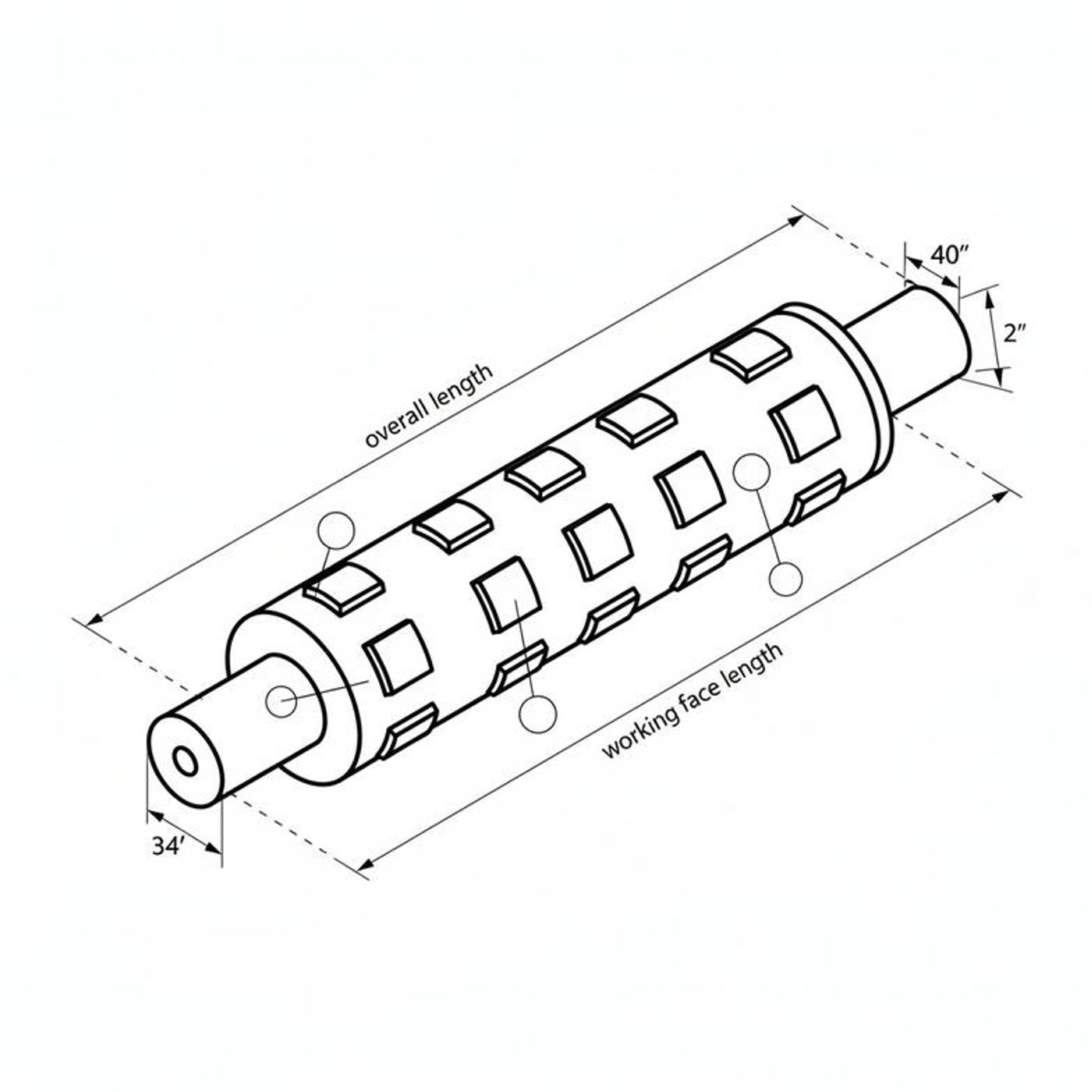
This might seem like a lot of detail, but gathering this information is the most reliable way to avoid a costly mismatch that leads to even more downtime. Let's break down exactly what your supplier needs to see and, more importantly, why each piece of information is so critical for getting the right part the first time.
Why Isn't a Photo and Model Number Enough for a Replacement Air Shaft?
It feels so simple, doesn't it? Just snap a picture of the old shaft, find the model number on the machine, and send it off. But what happens when the new shaft arrives and it looks right, but the journal is one millimeter too wide to fit in the bearing? Or the air valve is on the wrong end? Now you're back to square one, with more downtime and a part you can't use.
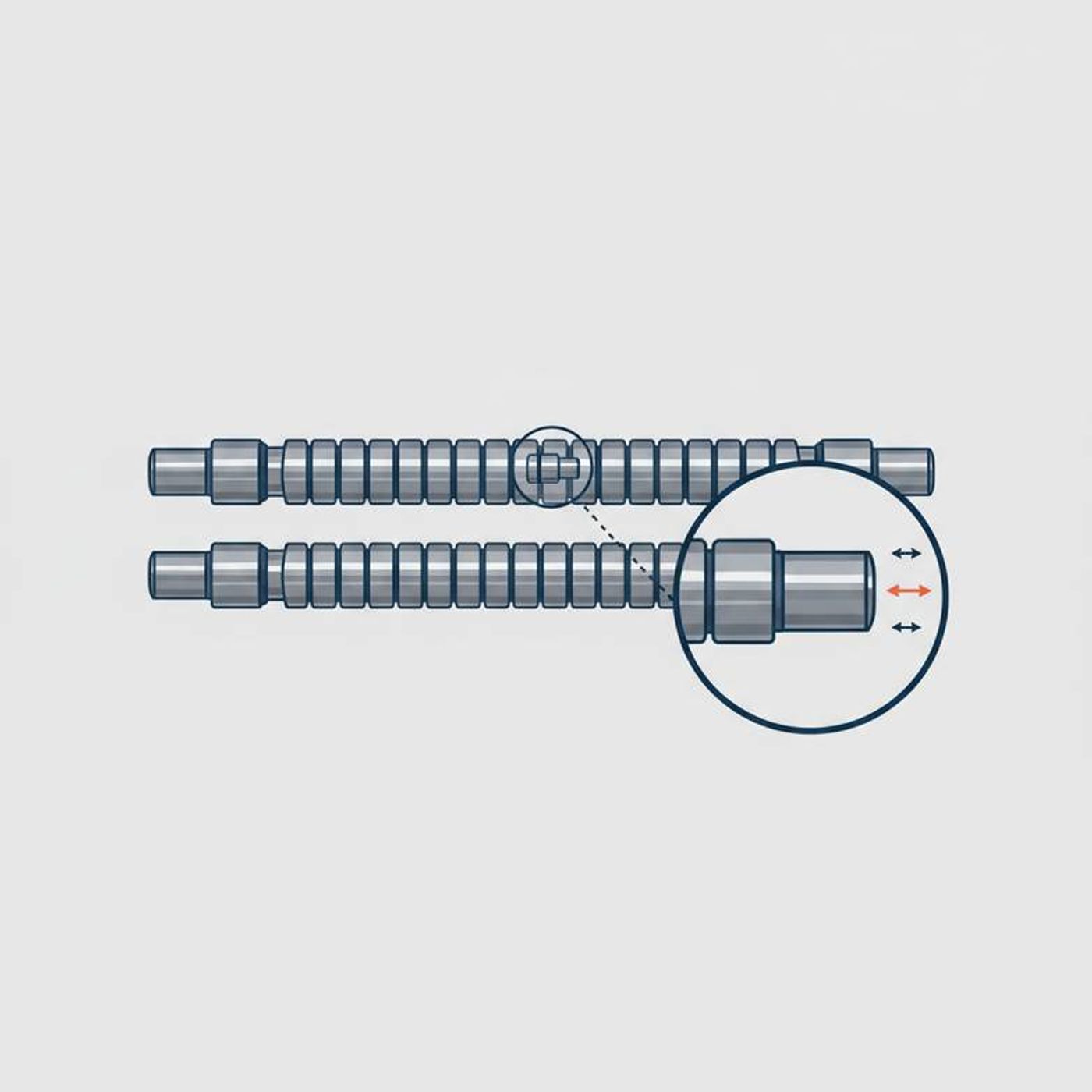
A photo and model number are not enough because they fail to capture the critical, non-visible details that determine compatibility. These include precise journal dimensions, bearing tolerances, the specific mounting method, or internal construction designed for a specific load. Manufacturers often make small but crucial custom modifications for different machine builders.
The Hidden World of OEM Customization
When a company like a slitter-rewinder manufacturer builds a machine, they often order air shafts from a specialist supplier with slight modifications. The shaft's model number might refer to a standard base model, but the version installed in your machine could have unique features.
I've seen this happen many times. A customer orders a shaft based on the model number in an old manual. The new shaft arrives, and it looks identical to the old one. But the journal—the end part that fits into the machine's chuck or bearing—was custom-machined for that specific machine builder. It's a fraction of a millimeter different, but that's all it takes to make it unusable.
These small differences can cause big problems:
- Journal Mismatches: A tiny difference in diameter means the shaft either won't fit at all or will be too loose, leading to heavy vibration that can damage your machine and the shaft itself.
- Mounting Interface Errors: Is your shaft a simple drop-in? Does it use a safety chuck? Is it cantilevered and supported on only one end? A photo rarely captures the details needed to match the mounting interface correctly.
- Air Valve Incompatibility: The air valve's location (on the end of the journal or through the side) and its thread type are critical. If it doesn't match, you won't be able to connect your air supply to inflate the shaft.
Don't Forget About Wear and Repair
The shaft you are replacing has been in service, possibly for years. It's entirely possible that a maintenance team has repaired or modified it in the past. Perhaps a journal was turned down on a lathe to fix a damaged surface. Measuring the existing shaft is the only way to know the dimensions your machine needs today, not the dimensions it had when it left the factory a decade ago.
What Are the Core Components of an Air Shaft Drawing?
So, you know you need to provide more than just a photo. But the thought of creating a "technical drawing" can sound intimidating if you're not an engineer. Don't worry. You can simplify the process by breaking the required information down into three logical groups. This ensures you cover all the bases without getting overwhelmed.
A complete and useful replacement air shaft drawing or sketch must clearly define three things: 1) the dimensions for mounting it in the machine, 2) the details for engaging with your material core, and 3) the operational data to ensure it performs correctly under load.
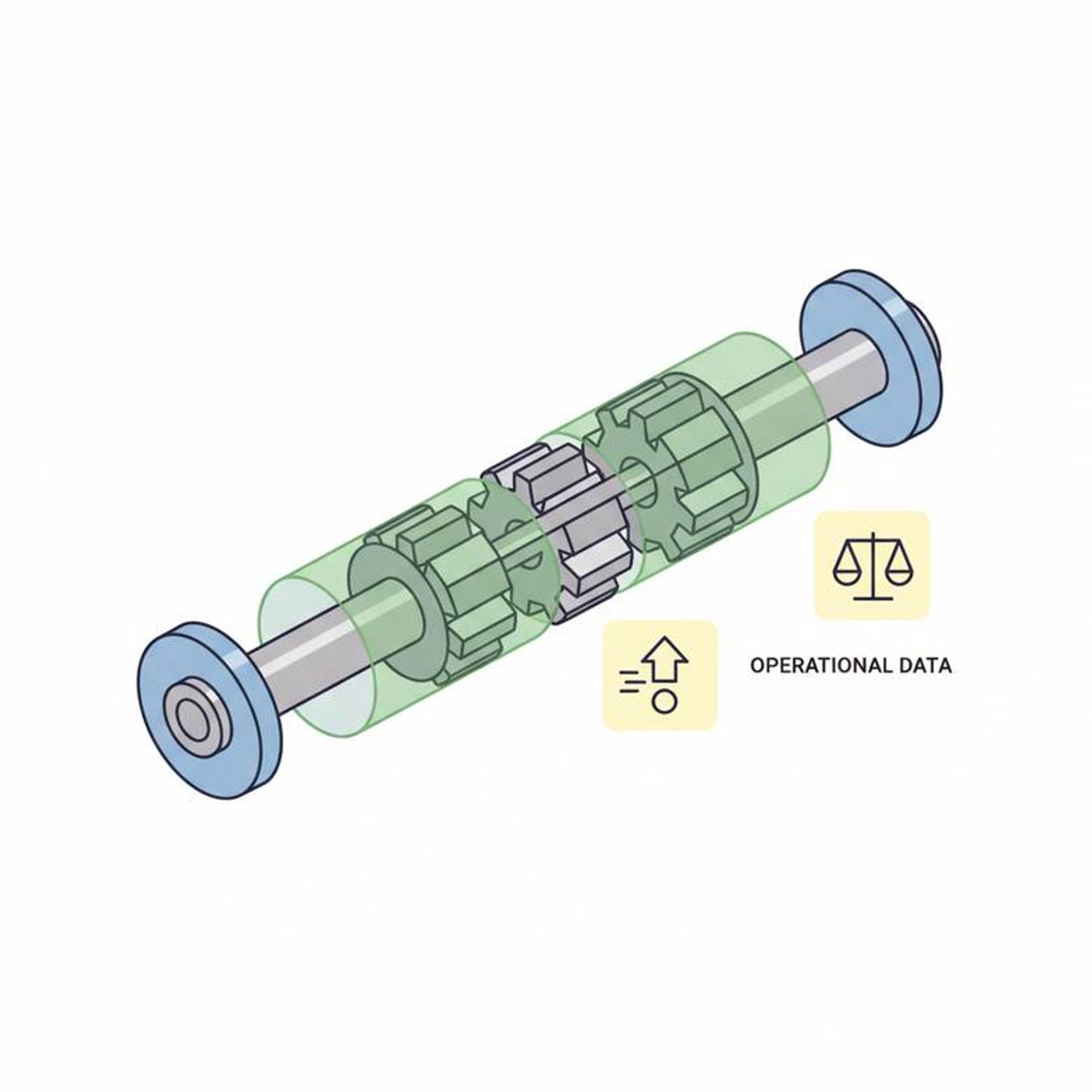
Part 1: Machine Interface — What the Machine Needs to See
This is all about making sure the shaft physically fits into your equipment. This is often where the most critical mistakes happen.
- Overall Length (OAL): The total length from one absolute end of the shaft to the other.
- Journal Dimensions: These are the machined ends of the shaft that sit in the machine's bearings, holders, or safety chucks. You'll need to measure the diameter and length of each stepped section on both ends. This is the most important measurement on the entire shaft.
- Air Valve Details: Where is the air valve located? Is it at the end of the shaft? Through the side of the journal? Take a close-up photo and note the thread size if you can.
Part 2: Core Engagement — What the Material Core Needs to See
This section covers the main body of the shaft, which is responsible for gripping the inside of the paper or film core.
- Working Face Length: This is the portion of the shaft body that makes contact with your material roll. It's the distance from the innermost expansion lug on one side to the other. This is different from the overall length.
- Shaft Body Diameter: The diameter of the main shaft body when it's deflated. This must be slightly smaller than your core's inner diameter so you can slide the core on and off easily.
- Core Inner Diameter (ID): Tell your supplier the ID of the cores you use (e.g., 3-inch or 6-inch are common, but always confirm your specific size).
- Lug Type and Material: Are the expanding elements long, continuous strips (leaf-type) or individual blocks (lug-type)? Are they made of rubber, aluminum, or steel? Leaf types are great for delicate cores, while steel lugs provide maximum grip for heavy paper rolls.
Part 3: Operational Data — How the Shaft Will Be Used
This information ensures the supplier provides a shaft that is strong enough and balanced correctly for your production needs.
- Maximum Roll Weight: The shaft must be engineered to support the weight of your heaviest roll without bending.
- Material Type: Are you running paper, plastic film, aluminum foil, or nonwoven fabric? Different materials create different torque requirements.
- Maximum Machine Speed: Higher operating speeds require shafts to be dynamically balanced to prevent vibration.
Here is a simple table to help you gather the information:
- Information Category: 1. Machine Interface | Key Dimensions & Data: Overall Length, Journal Diameters & Lengths, Air Valve Info | Why It's Critical: Ensures the shaft physically fits and connects in your machine.
- Information Category: 2. Core Engagement | Key Dimensions & Data: Working Length, Body Diameter, Lug Type, Core ID | Why It's Critical: Ensures the shaft can properly grip and release your material core.
- Information Category: 3. Operational Load | Key Dimensions & Data: Max Roll Weight, Material Type, Machine Speed | Why It's Critical: Ensures the shaft is strong enough and balanced for your application.
How Do I Create a Sketch for a Replacement Air Shaft if I Don't Have a Drawing?
You've searched everywhere, but the original drawing for your air shaft is gone. You might feel stuck, but you're not. A clear, well-measured sketch made by hand is often more than enough for a good supplier to create a formal drawing for your approval.
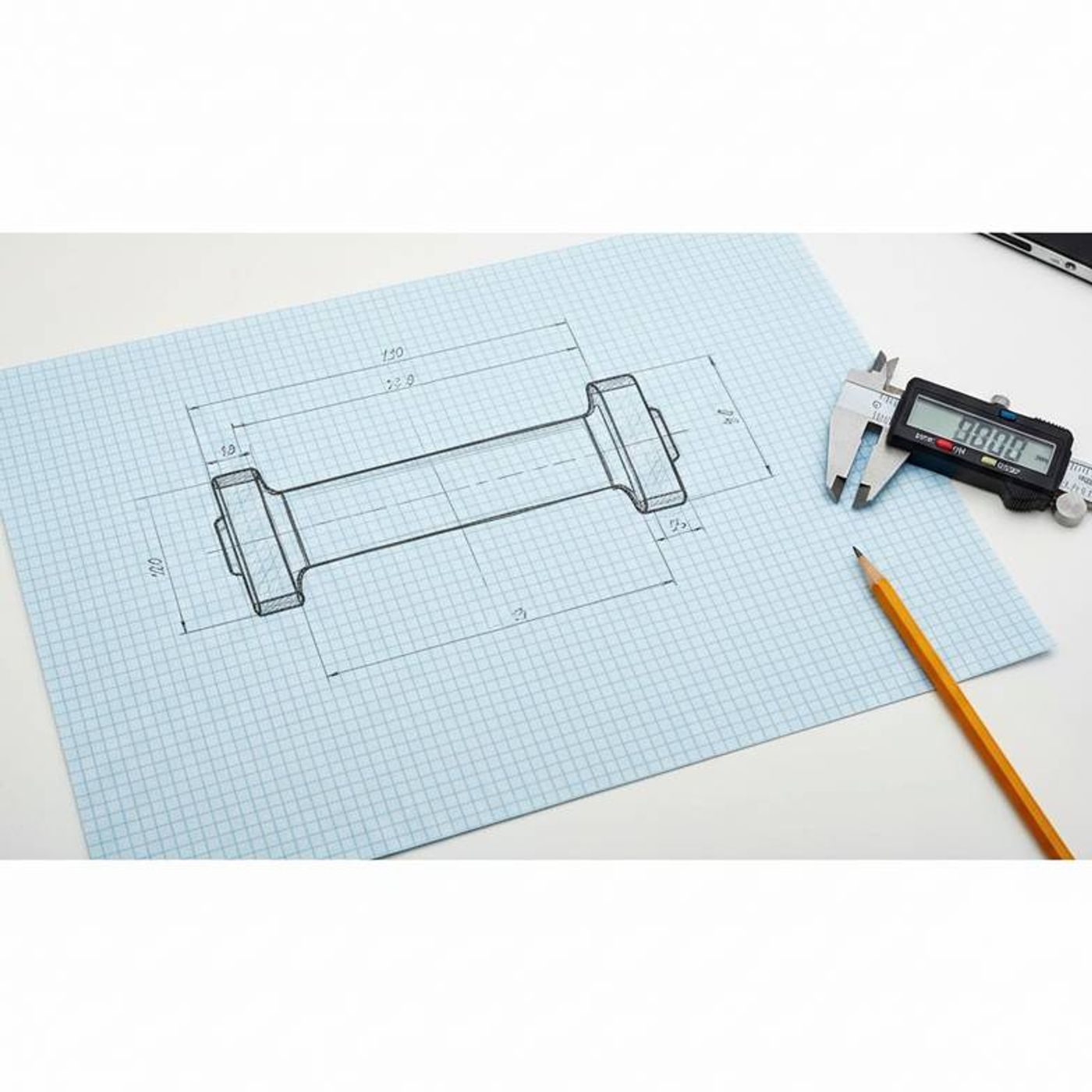
To create a useful sketch for a replacement air shaft, you'll need to methodically measure the old shaft using calipers and a tape measure. Then, draw a simple diagram and clearly label all the key dimensions you recorded, paying special attention to the journals at each end.
Your Toolkit for Measurement
You don't need a full machine shop, but a few basic tools are essential for accuracy.
- Digital Calipers: This is non-negotiable for getting precise measurements of the journal diameters.
- Tape Measure: For longer measurements like overall length and working face length.
- Paper and Pen: For the sketch itself.
- Smartphone Camera: For taking clear photos of the journals and air valve.
A Step-by-Step Guide to Measuring Your Shaft
- Lay It Out: Place the shaft on a flat, stable surface where you can access it easily.
- Measure the Big Picture: Use your tape measure to get the Overall Length from tip to tip. Then, measure the Working Face Length.
- Focus on the Journals: This is where your calipers are essential. For each end of the shaft:
- Measure the diameter of every section of the journal. Write it down immediately. Even a small step-down is important.
- Measure the length of each of those sections.
- Take clear, well-lit photos of each journal. Capture any keyways, flats, or threaded holes used for mounting.
- Document the Air Valve: Note its location and take a close-up photo. If you know the thread size, write that down too.
- Sketch It Out: You don't need to be an artist. Draw a long rectangle for the shaft body. Draw the stepped journals on each end. Now, label every single dimension you measured directly on your sketch. Clarity is more important than beauty.
The Most Important Step: The Confirmation Drawing
Here’s a critical piece of advice that protects you, the buyer. You send your sketch, your photos, and your operational data to your supplier. A trustworthy supplier, like us at DJH Machinery, will not just start building the shaft from your hand-drawn sketch.
Instead, we will use your information to create a formal, professional engineering drawing. We then send this confirmation drawing back to you for your final approval before production begins.
This step is your ultimate safety net. It gives you the chance to review all the critical dimensions one last time. It ensures that both you and the supplier are in complete agreement on what is being built. Never, ever place an order with a supplier who is not willing to provide a confirmation drawing for your approval.
Frequently Asked Questions
Can I just replace the expanding lugs or air bladder?
In many cases, yes. Components like lugs, journals, and internal air bladders are often serviceable parts. You will still need to identify the shaft's key dimensions to ensure you order the correct parts. It's a good idea to discuss with your supplier whether a component repair or a full shaft replacement is more cost-effective in the long run.
What's the difference between a lug-type and a leaf-type air shaft?
Lug-type shafts have individual metal or rubber "buttons" that expand to grip the core. They offer very high torque and are excellent for heavy-duty materials like paper and foil. Leaf-type shafts use long, continuous metal strips that provide a more uniform, 360-degree grip. This makes them ideal for delicate films and thin-walled cores that could be damaged by focused pressure points.
How do I measure the journals accurately without calipers?
While calipers are strongly recommended for getting a precise measurement, if you absolutely don't have access to them, you must inform your supplier. You can try to get close with a high-quality steel ruler, but there is a significant risk of error. It's better to tell your supplier "this measurement is approximate" so they know to pay extra attention to it on the confirmation drawing.
How long does it take to manufacture a custom replacement air shaft?
Production time can vary significantly based on the shaft's complexity, the materials required, and the supplier's current production schedule. A typical timeframe might be anywhere from 3 to 6 weeks. This is exactly why providing complete and accurate information upfront is so vital—it avoids back-and-forth questions and gets your order into the production queue as quickly as possible.
Conclusion
Ordering a replacement air shaft doesn't have to be a stressful guessing game. It’s not about finding a single, elusive OEM drawing. Instead, it's about systematically gathering and providing a complete set of information that covers the machine interface, the core engagement, and your operational loads. A detailed sketch, combined with clear photos and your roll specifications, is a powerful tool. Above all, remember that the most important step in the entire process is your final review and approval of the confirmation drawing from your supplier. This collaborative approach is the best way to eliminate risk, prevent costly compatibility errors, and get your production line back up and running with a part you can depend on.
If you are preparing to source a replacement air shaft and want to ensure you get a perfect fit, our team at DJH Machinery is here to help. Send us your sketch, photos, and operational details, and we will work with you to create a detailed confirmation drawing for your review.