Air-Expanding Rewind Shafts
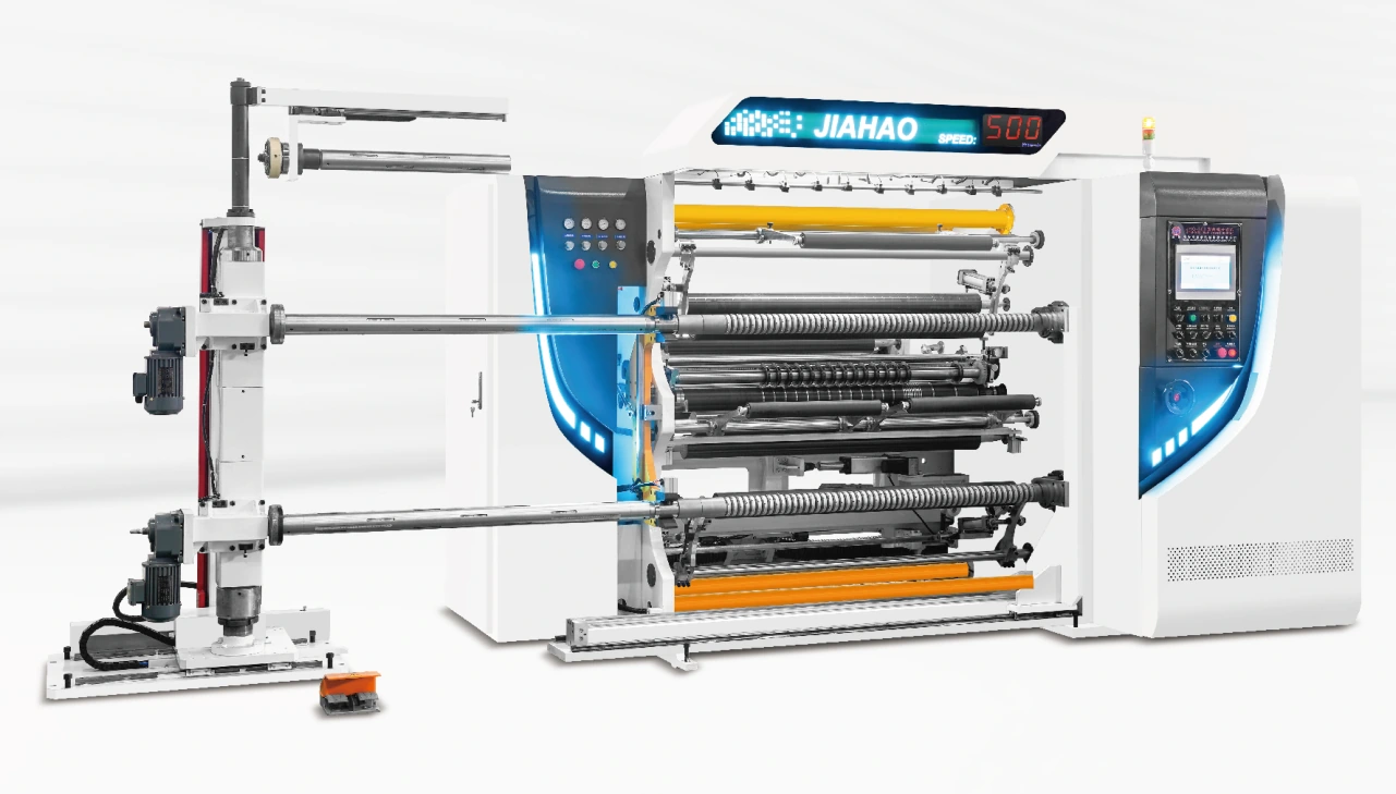
Air shafts grip the cores during rewinding. Core inside diameter, core condition, shaft loading and the planned finished-roll mass determine the interfaces to review.

SLITTING & REWINDING · QFJ-A200
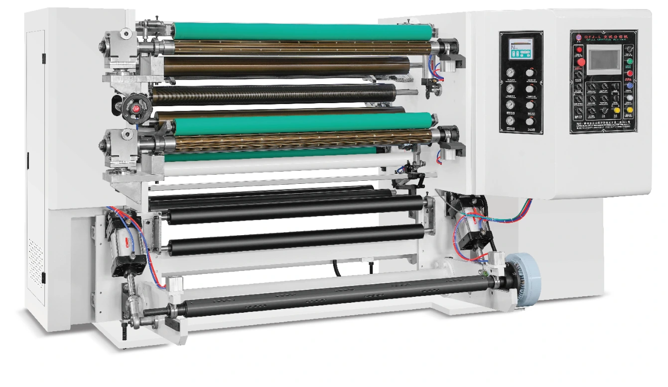
Compare an integrated horizontal configuration using air-shaft rewinding and separate magnetic-powder tension control for each winding shaft. The A200 lists a 200 m/min slitting speed with a 1,000 mm parent-roll diameter and 600 mm finished-roll diameter.
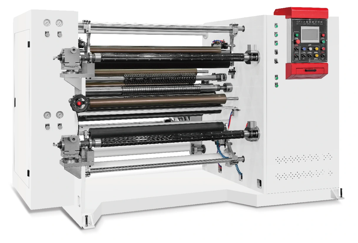
Listed configuration values. Production speed and practical slit pattern depend on the material and the agreed machine setup.
Start with A200 when the incoming roll, finished format and target production conditions fit the 200 m/min configuration. Evaluate the required tension behaviour and roll firmness alongside the horizontal web path. Selecting this model should be based on the actual converting task rather than treating a lower headline speed as the only difference.
CONSTRUCTION & CONTROL
Air shafts grip the cores during rewinding. Core inside diameter, core condition, shaft loading and the planned finished-roll mass determine the interfaces to review.
Each winding shaft has separate magnetic-powder tension control. Confirm control range and winding requirements for the actual material and roll build instead of assuming the servo arrangement of another model.
The integrated construction provides a horizontal converting path. Review threading positions, knife access, floor space and the route used to load and remove rolls.
The 1,300 and 1,800 mm configurations share the listed roll diameters and minimum slit width. The wider version has a different main motor rating, which should be included in the electrical review.
MATERIAL & FINISHED ROLL
Specify grade, grammage, slit pattern and downstream use. Include dust, coated-surface marking or winding hardness among the acceptance checks where relevant.
PVC, BOPP, CPP, PET and composite webs should be reviewed by thickness, layer structure and stretch. Determine whether the contact and tension arrangement suits the finished roll.
Provide grade, temper and thickness, along with allowable edge defects. Agree the knife setup and trial conditions for the foil rather than relying on a general material listing.
WIDTH & DRIVE CONFIGURATIONS
| Parameter | 1300 configuration | 1800 configuration |
|---|---|---|
| Unwinding width | 1,300 mm | 1,800 mm |
| Listed slitting speed | 200 m/min | 200 m/min |
| Minimum slit width | 20 mm | 20 mm |
| Parent-roll diameter | 1,000 mm | 1,000 mm |
| Finished-roll diameter | 600 mm | 600 mm |
| Main motor power | 5.5 kW | 7.5 kW |
Drive powers are individual motor entries, not the total installed electrical load. Confirm voltage, frequency, utilities, roll weight and core interfaces with the proposed supply. Required material thickness and production tolerances are application-specific.
SETUP, OPERATION & ACCEPTANCE
Provide parent width, diameter, mass and core, then specify each finished width, core and diameter.
Review blade arrangement, web guidance and magnetic-powder tension requirements with the material and lane pattern.
Assess edge quality and winding firmness as diameter builds. Record operating conditions so the trial result can be compared with the agreed supply.
Review safe threading, roll removal and access to wear parts. Keep the shaft and blade interface information available for replacement inquiries.
Review the floor plan, service clearance, roll-handling route and utilities before installation. Agree commissioning and operator-training requirements with the proposal. Keep the machine identification, shaft interfaces and blade dimensions available for maintenance and spare-part inquiries.
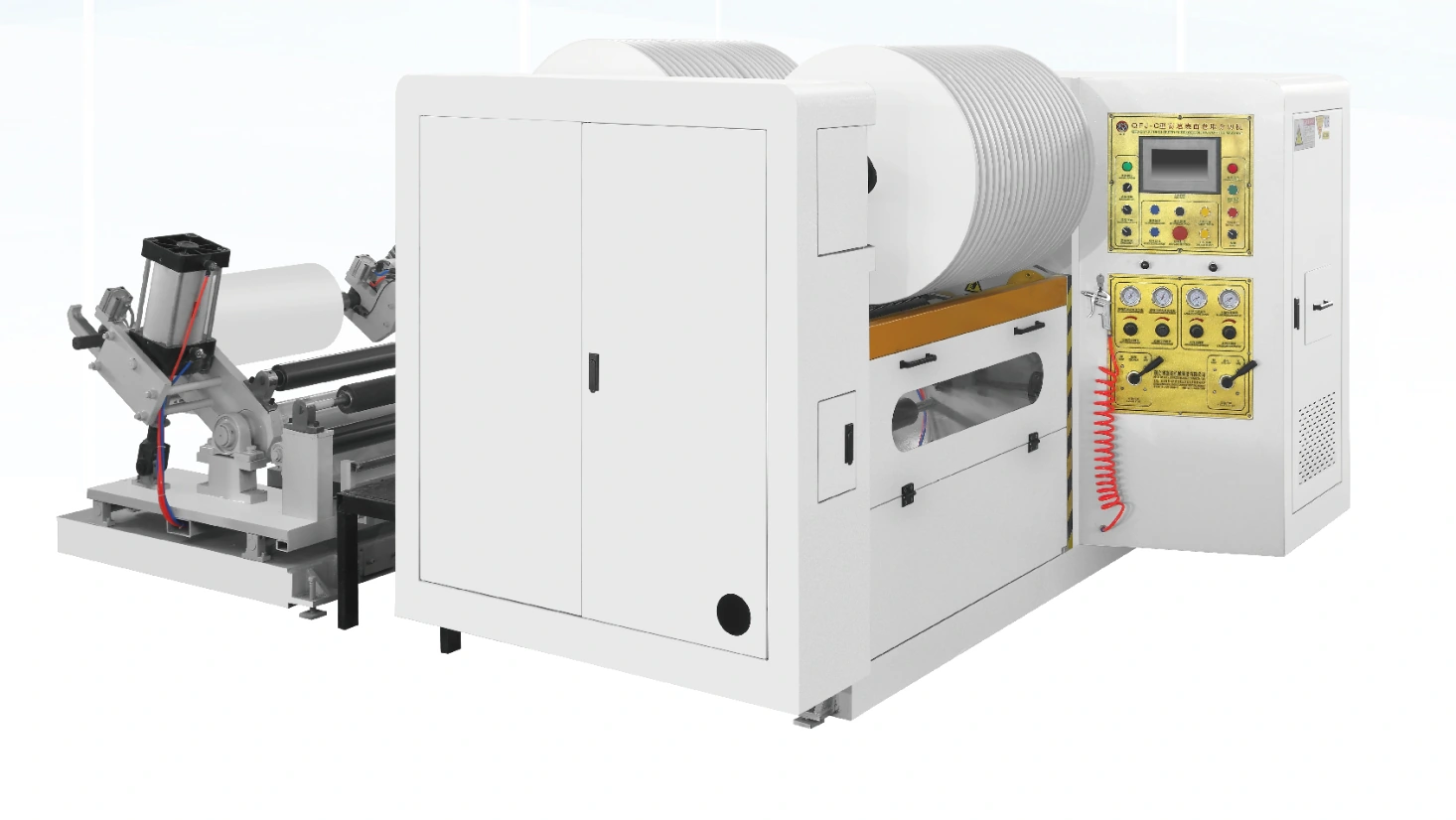
Compare A200 with B200 for horizontal versus vertical layouts and roll capacity: B200 lists a 700 mm parent diameter and 400 mm finished diameter. Compare A500 where differential shafts and servo-controlled winding are relevant. These are different constructions, not merely different speed settings.
BEFORE YOU SPECIFY
The winding shafts in this configuration use separate magnetic-powder tension control. Confirm the complete drive and control scope in the proposed specification.
It is the listed speed. Material behaviour, slit pattern, roll condition and finished-roll requirements determine the practical operating range.
Confirm supply voltage and frequency, total connected load and the control and auxiliary equipment supplied. The table lists the main motor entry only.
Include the actual web width and trim requirements in your inquiry. Any alternative width and its associated drive, loading and winding conditions need a matching proposal.
QUOTATION & SUPPLY SCOPE
Request a QFJ-A200 quotation against your material, working width and finished-roll targets. Identify the selected version, cutting and winding arrangement, loading equipment and controls in the proposed supply.
Ask for standard equipment and optional items to be listed separately. Include commissioning, operator training, documentation and initial spare-part requirements in the discussion.
Provide quantity and destination. Confirm price, currency, delivery basis, packing, production schedule and any excluded freight or import charges in the quotation.
Agree representative material inspection, measurement criteria and supplied configuration before ordering. Confirm warranty terms, installation responsibilities and spare-part support with the proposal.
COMPARE MACHINE FORMATS
YOUR MATERIAL. YOUR FINISHED ROLL.
Share the web construction, incoming roll, slit pattern and finished-roll requirements. Include the information you already have.